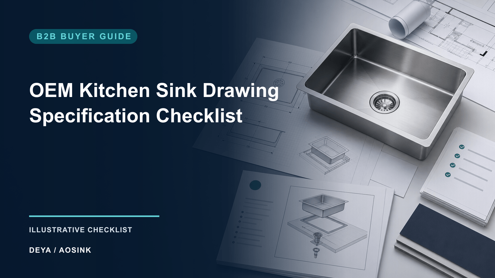
An OEM kitchen sink drawing should tell the factory what must be made and tell the inspector what must be measured. A quotation-ready drawing needs more than overall length and width. It should define the bowl, rim, corners, drain, holes, installation interface, finish, accessories, tolerances and revision status.
This guide helps B2B buyers prepare a controlled drawing package before requesting tooling, samples or production. It does not provide universal sink dimensions; those depend on the buyer’s cabinet, countertop, plumbing, market and product strategy.
Start with the intended installation
State whether the sink is topmount, undermount, flush-mount, apron-front or another agreed configuration. The same visible bowl can require a different flange, cut-out and mounting method. Add a section view that shows how the sink meets the countertop and where sealant or hardware is expected.
Identify the target cabinet or cut-out constraints separately from the sink’s finished dimensions. This prevents the factory from treating a cabinet size as if it were the sink size.
Drawing title-block essentials
- Buyer SKU and product name
- Drawing number, revision and issue date
- Measurement units
- Scale or “not to scale” statement
- Material and finish specification reference
- General tolerance, plus specific tolerances where needed
- Prepared, checked and approved names or roles
- Change summary for each revision
Never send an unlabeled sketch and later assume it became the production drawing. A revision code gives the purchase order, sample and inspection report one common reference.
Define the overall envelope
Show the finished overall length, width and height. Add the bowl depth and any deck, apron or rear-ledge dimensions. If the sink has an unusual outline, dimension the controlling angles, flats and radii from stable datums instead of chaining many small dimensions.
Avoid over-dimensioning. Two conflicting dimension chains create ambiguity. Choose datums that the factory and inspector can locate consistently, then measure critical features from those references.
Dimension the bowl and corners
Define the bowl opening and internal geometry required for function and appearance. Include corner radii where they affect cleaning, forming, welding, accessory fit or visual identity. Show transitions and side-wall angles when they matter.
The article image shows an angular bowl with a broad rim and multiple deck holes. It is useful for explaining geometry, but it is not a dimensional reference. Every production dimension must come from the approved drawing.
Control the drain location
Locate the drain opening from clear datums and state the finished opening requirement. If the drain is offset, define direction relative to the front or rear of the sink. Confirm the required waste fitting separately; a drain-hole dimension alone does not define the complete plumbing kit.
Consider under-counter conflicts such as drawers, cabinet partitions, waste disposers or plumbing routes. These are buyer-side installation constraints and should be communicated before the design is frozen.
Specify faucet and accessory holes
For each hole, record diameter, center coordinates, quantity and purpose. Distinguish factory-punched holes from optional knockouts or buyer-site drilling. Check edge distance and under-deck clearance for the intended faucet, soap dispenser, cup washer, control or filtration tap.
A row of holes that looks balanced in a rendering may still conflict with clips, bowl walls or plumbing. The drawing should include enough section or underside information to review mounting clearance.
Define the rim, flange and cut-out interface
Show rim width, flange flatness requirement where applicable, corner shape and mounting details. For an undermount product, provide the intended reveal condition and a controlled cut-out template. For a topmount product, show the visible rim and the part of the bowl that must pass through the opening.
Do not publish a cut-out value until it has been checked against an approved physical sample. Installers need a verified template, not a marketing image.
Separate material from appearance
Material grade, sheet requirement and verification method belong in the drawing or referenced specification. Surface appearance belongs in a finish specification or approved sample. A brushed pattern, coating color or texture does not establish the underlying alloy.
ASTM A240/A240M covers several families of stainless plate, sheet and strip and includes chemical-composition and mechanical-property requirements. If it is used in a purchase specification, state the exact grade and evidence required; citing the standard alone is incomplete.
Add accessory-interface dimensions
For workstation sinks, dimension ledges and the usable travel path for boards, colanders, racks and trays. Define accessory size, support area and clearance. A nominal bowl width cannot guarantee accessory interchangeability.
For bottom grids, baskets or drain covers, identify the relationship to the drain and bowl corners. Attach a controlled accessory drawing or component list instead of describing the item only by name.
Use tolerances selectively
Not every dimension needs the same tolerance. Classify dimensions by consequence:
| Dimension type | Risk if wrong | Control approach |
|---|---|---|
| Installation critical | Sink or hardware does not fit | Specific tolerance and sample verification |
| Accessory interface | Board, rack or drain part is unstable | Paired part check and functional gauge where useful |
| Cosmetic geometry | Visible inconsistency | Drawing plus approved visual sample |
| Noncritical reference | Low functional impact | Mark as reference; do not use for acceptance |
Ask the manufacturer whether the proposed process can hold the requested tolerance. An unnecessarily tight tolerance can add cost without improving installation or user value.
Create a complete drawing release package
- 2D drawing with revision control
- 3D file where needed, with a stated order of precedence
- Material and finish specification
- Accessory component list and interface drawings
- Cut-out or installation template
- Approved sample record
- Inspection checklist linked to drawing characteristics
State which document governs if the 2D drawing, 3D file and sample conflict. Resolve the conflict before production rather than asking the factory to choose.
Frequently asked questions
Can a sink factory quote from a reference photo?
It can provide a preliminary estimate, but a comparable final quotation needs controlled dimensions, material, finish, accessory and packaging scope.
Should every sink dimension be inspected?
No. Identify critical, major and reference dimensions based on installation, function and appearance risk. The inspection plan should focus effort where variation causes real loss.
Who owns the OEM drawing?
Ownership depends on the commercial agreement and applicable law. Put tooling, design-file access, permitted use and confidentiality terms in the contract rather than assuming them.
When should the drawing revision change?
Change the revision whenever an approved requirement changes, including dimensions, holes, accessories, material, finish or installation interface. Record the reason and approval.
No responses yet